1300 804 552
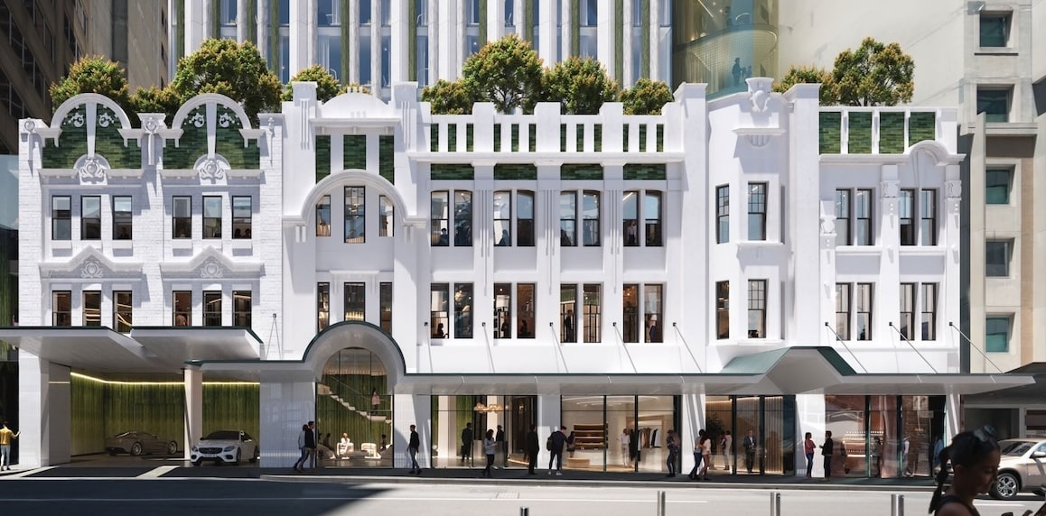
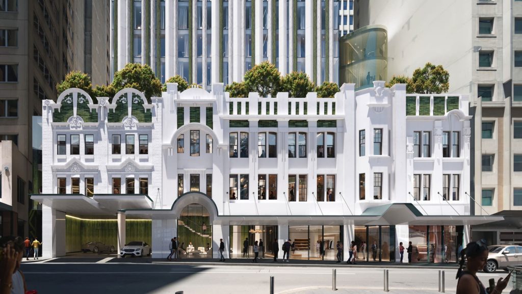
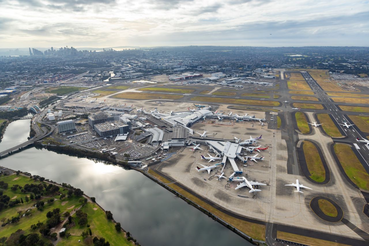
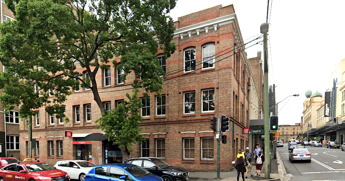
Assessing Structural Integrity: The 372-382A Pitt Street Hotel Redevelopment
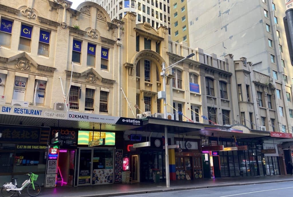
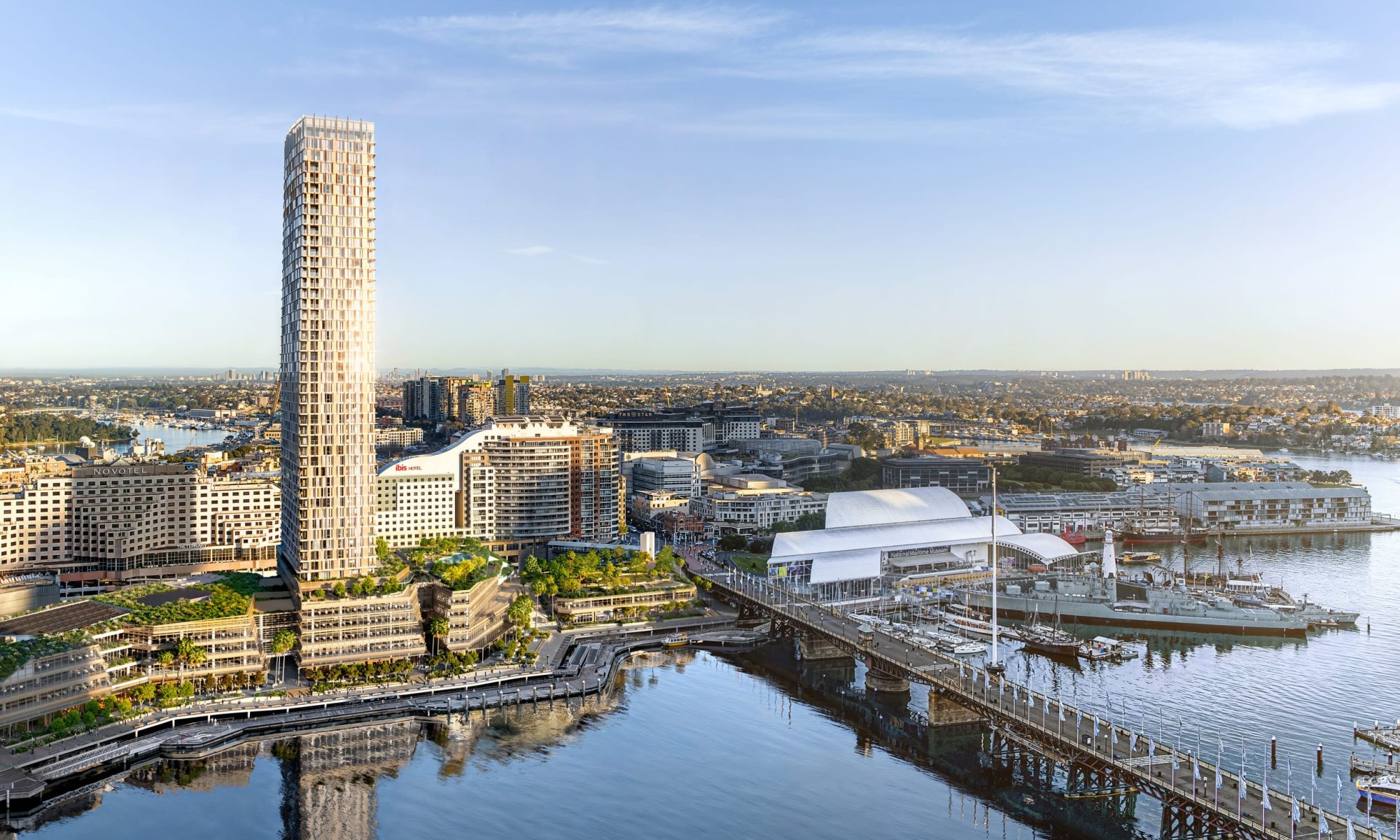
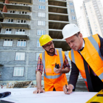
In the heart of Sydney, redevelopment projects blend heritage preservation with modern innovation. Well Smart Group engaged BCRC Durability Consultants to assess the structural conditions at 372-382A Pitt Street, an ambitious project involving significant redevelopment while retaining a historic façade.
Project Scope and Purpose
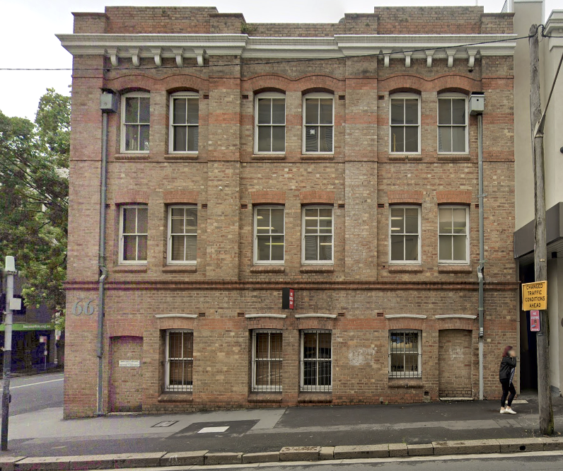
The redevelopment includes the construction of a new 60-storey hotel tower with a 4-storey mixed-use podium. BCRC’s inspection focused on the structural integrity of the retained front 6 metres of the existing buildings, including the façade. Comprehensive site assessments were conducted using a combination of advanced non-destructive (NDT) and destructive testing methods.
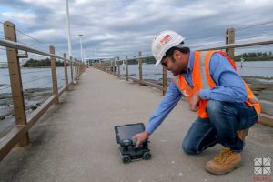
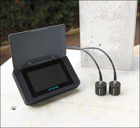
Key Inspection Methods
BCRC’s thorough assessment employed:
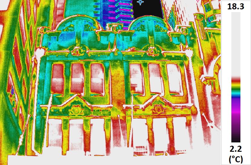
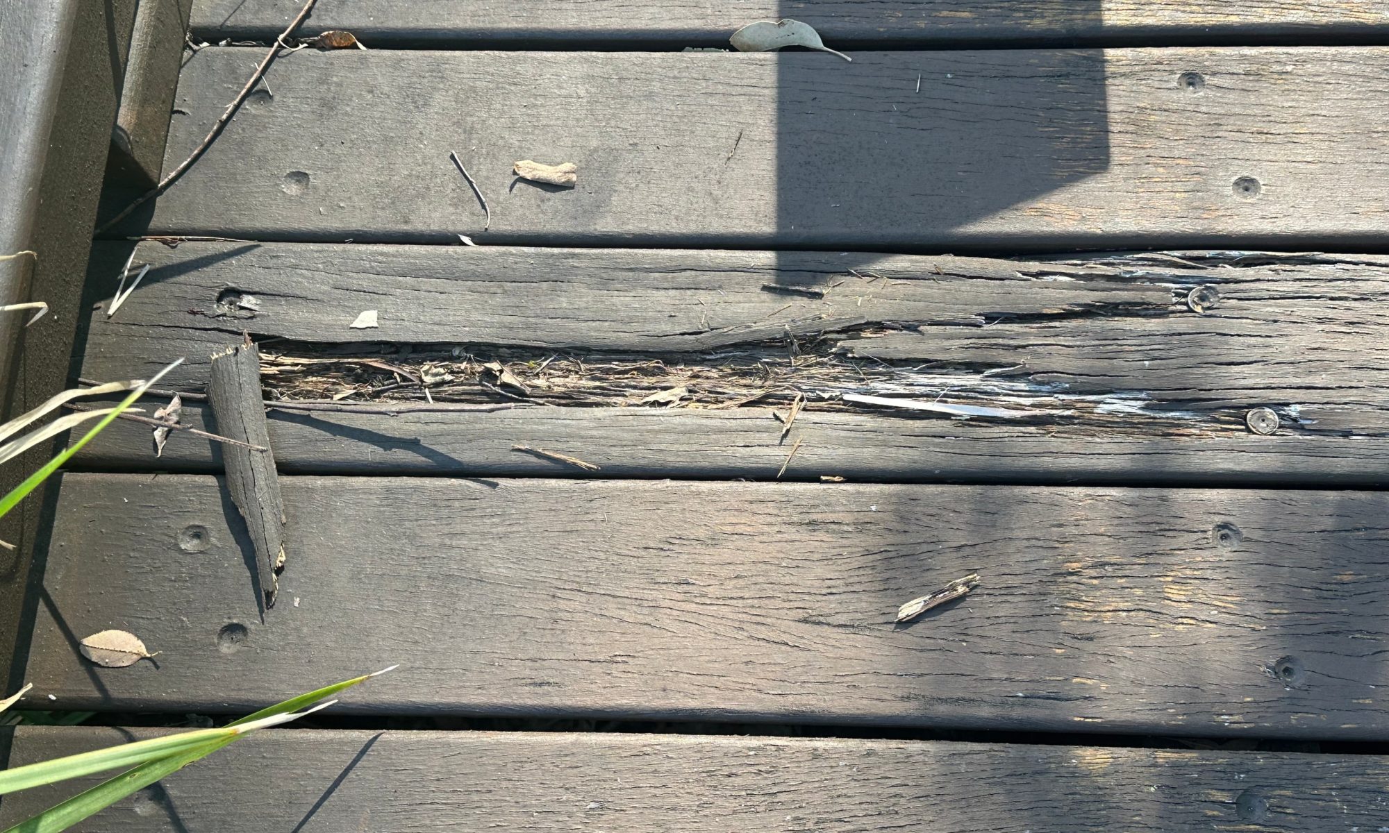
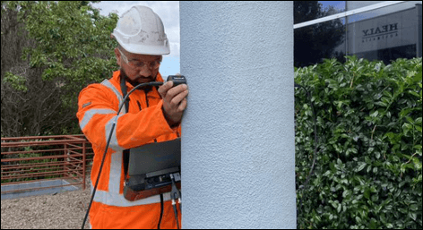
- Visual and thermal imaging inspections
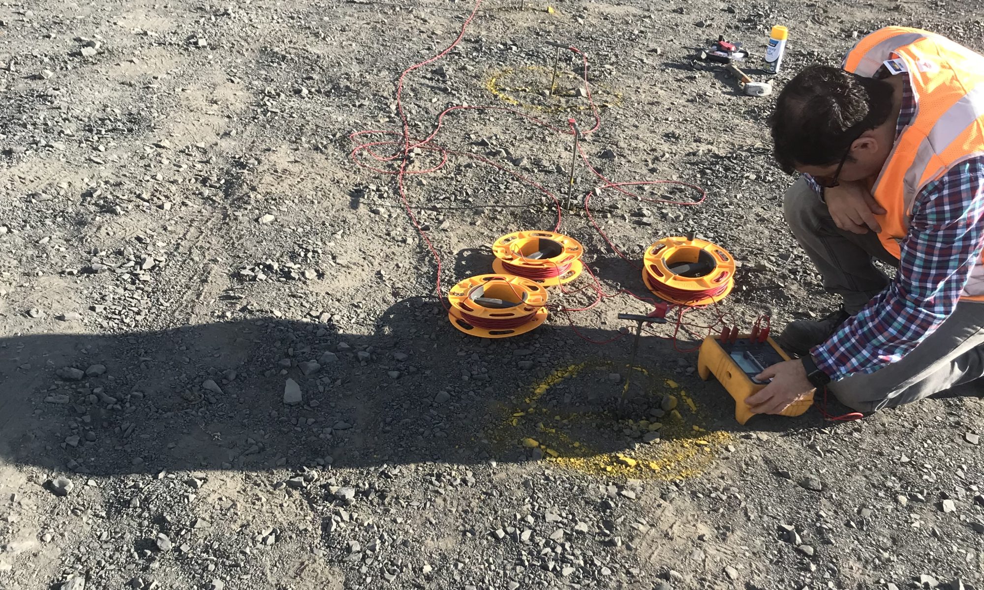
- Ground Penetrating Radar (GPR) for concrete cover and reinforcement detection
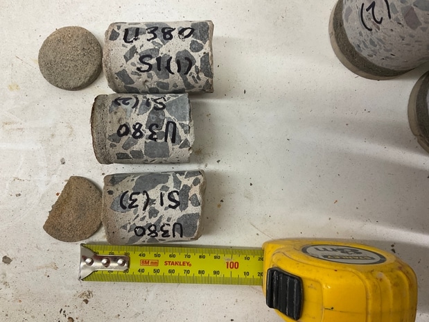
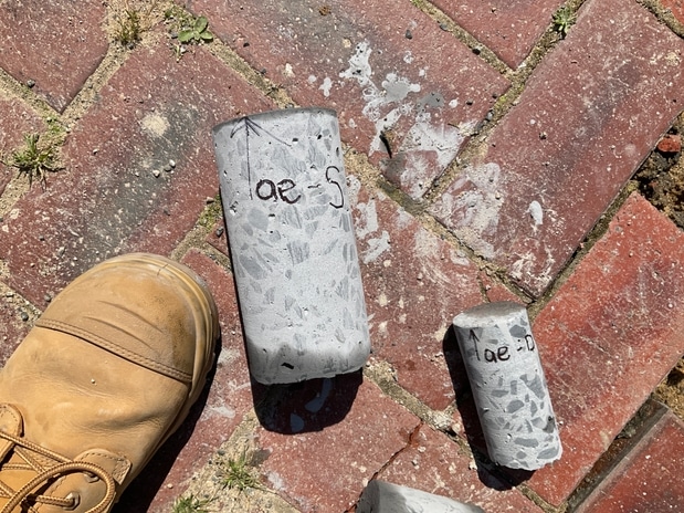
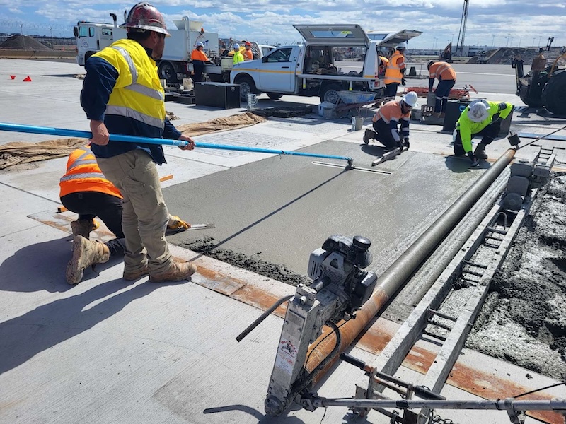
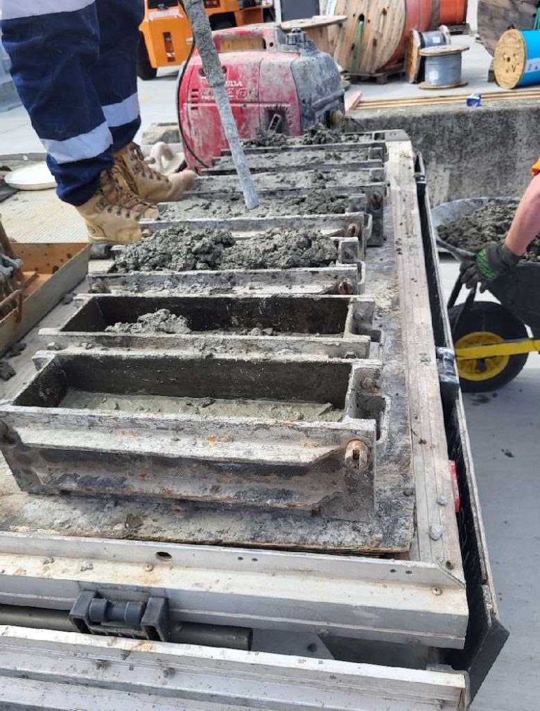
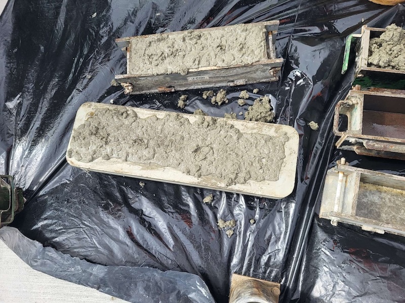
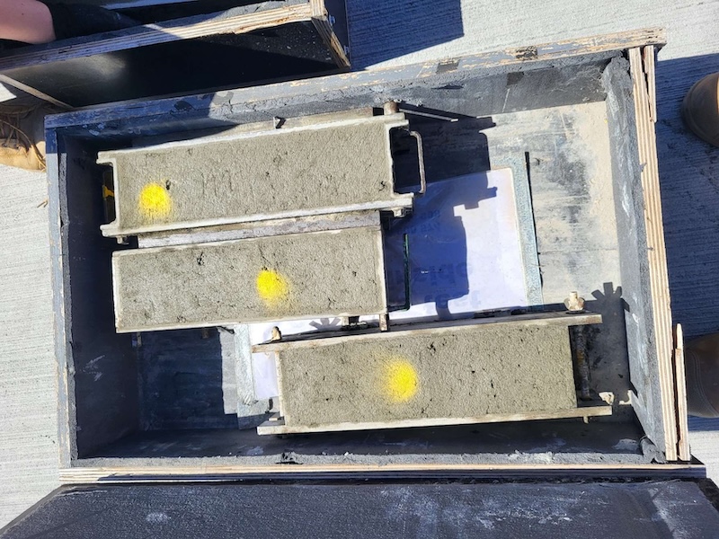
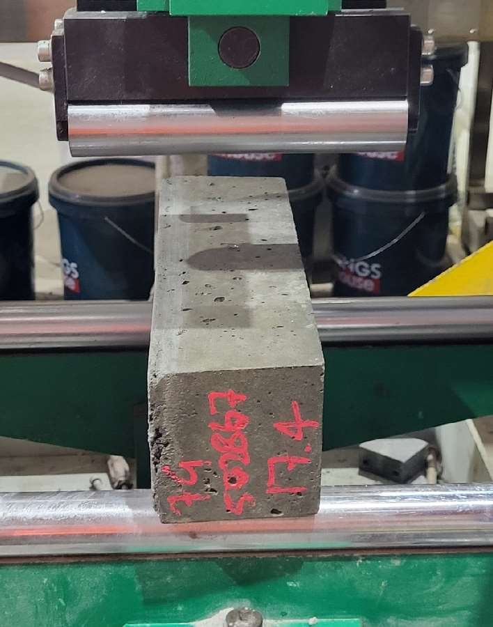
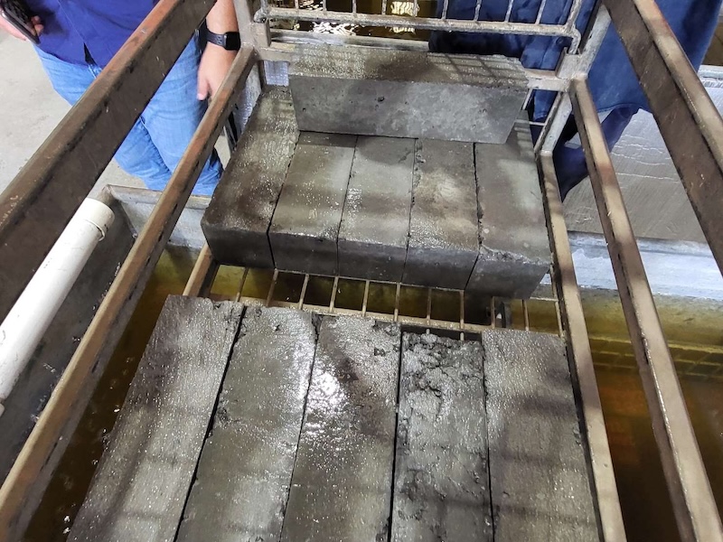
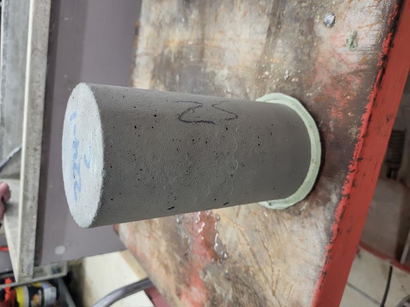
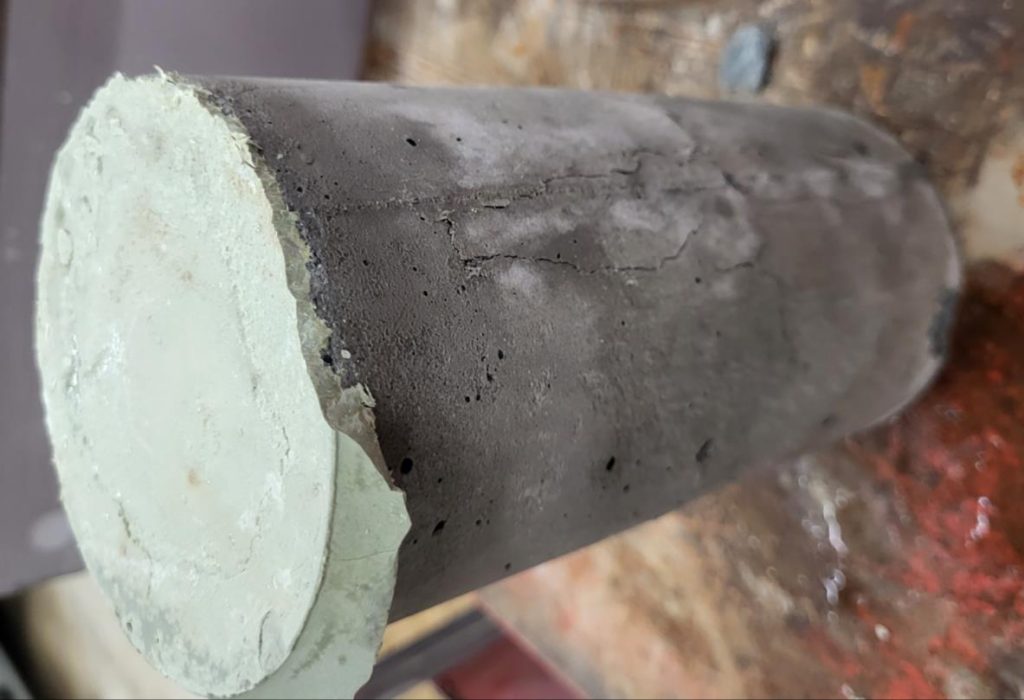
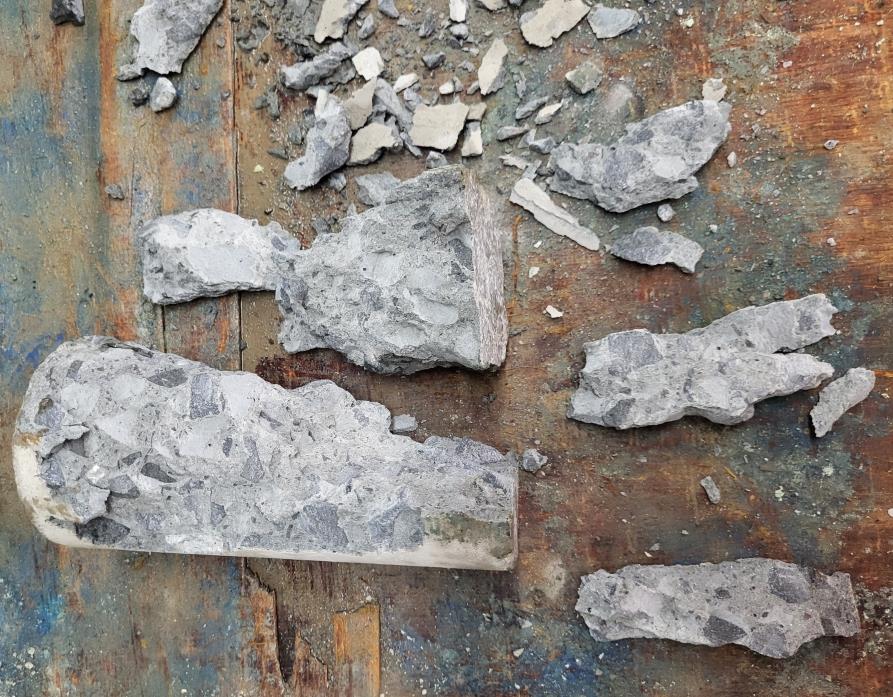
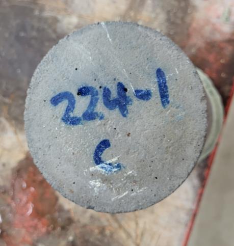
- Core sampling for compressive strength and chemical analyses
- Masonry tests, including compressive strength, mortar scratch tests, and bond wrench tests
- Foundation assessments through visual inspection and coring
Enhanced Structural Condition Assessment and Targeted Remediation Measures
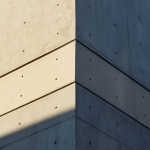
Façade and Masonry Walls
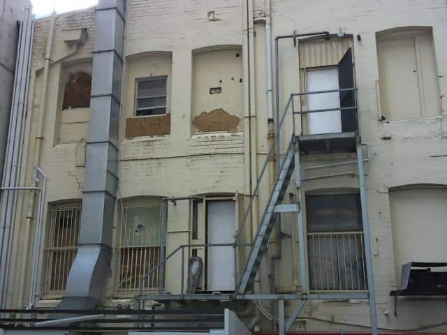
The façade demonstrates overall structural soundness, constructed using traditional staggered brick bonding. While the absence of modern cavity ties presents an opportunity for moisture control improvements, the structure remains fundamentally intact.
To ensure optimal long-term performance, the following enhancements are being implemented:
· Façade Upgrades: Immediate repair works include sealing of cracks, selective brick replacement, and the application of advanced waterproofing solutions to prevent moisture ingress.
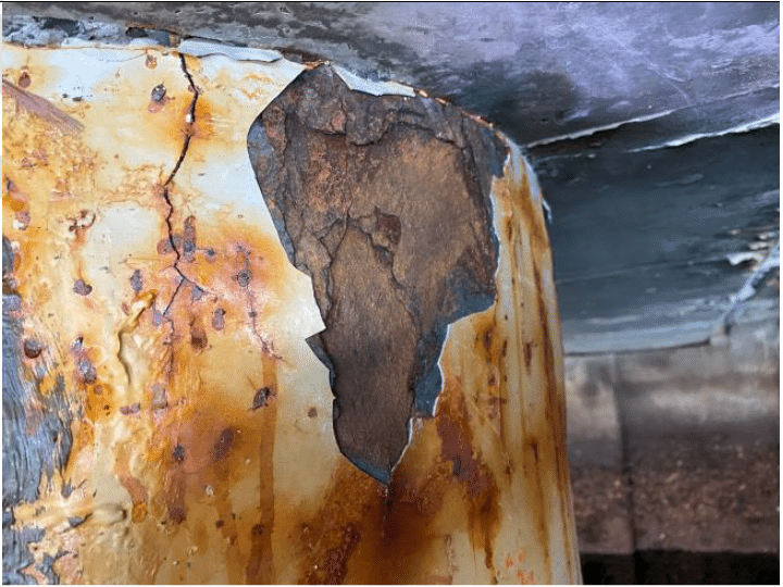
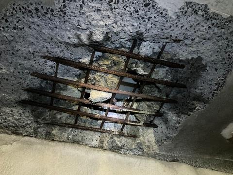
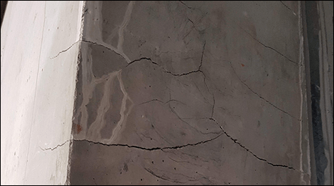
· Masonry Wall Rehabilitation: Despite adequate compressive strength, areas exhibiting cracked bricks and deteriorated mortar joints are undergoing repointing and localised brick replacement, reinforcing both strength and appearance.
Concrete Slabs
The concrete slabs exhibit adequate structural capacity, indicating sound original construction.
In order to maximise service life and mitigate isolated issues, the following steps are underway:
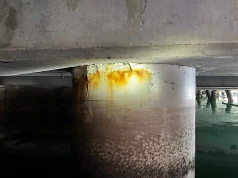
· Contamination Control: Localised remediation is being conducted on the affected unit to address potential contamination.
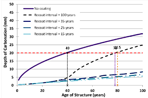
· Corrosion Prevention: With chloride and carbonation levels found to be low, corrosion risk is currently minimal; however, monitoring systems are being introduced to ensure early detection of any future changes.
· Structural Reinforcement Planning: A load-bearing capacity assessment has been conducted to identify potential issues and rectify them.
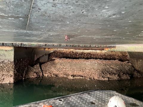
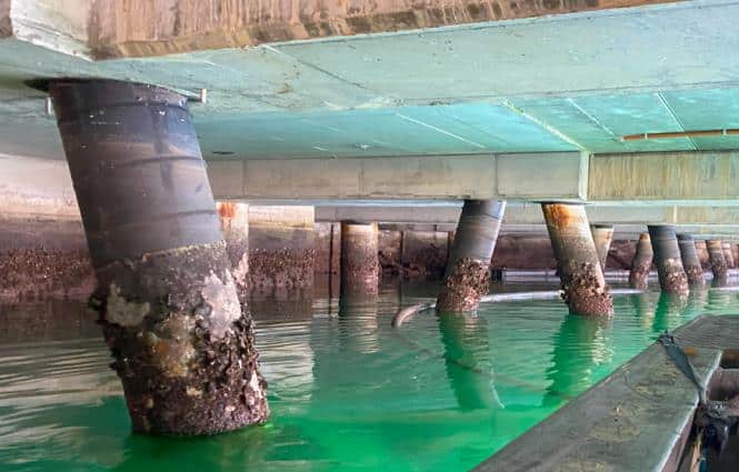
Foundations
The existing continuous strip footings beneath the retained sections were found to be stable and performing well. Minor cracking has been noted and will be monitored as part of ongoing maintenance, ensuring early intervention if required.
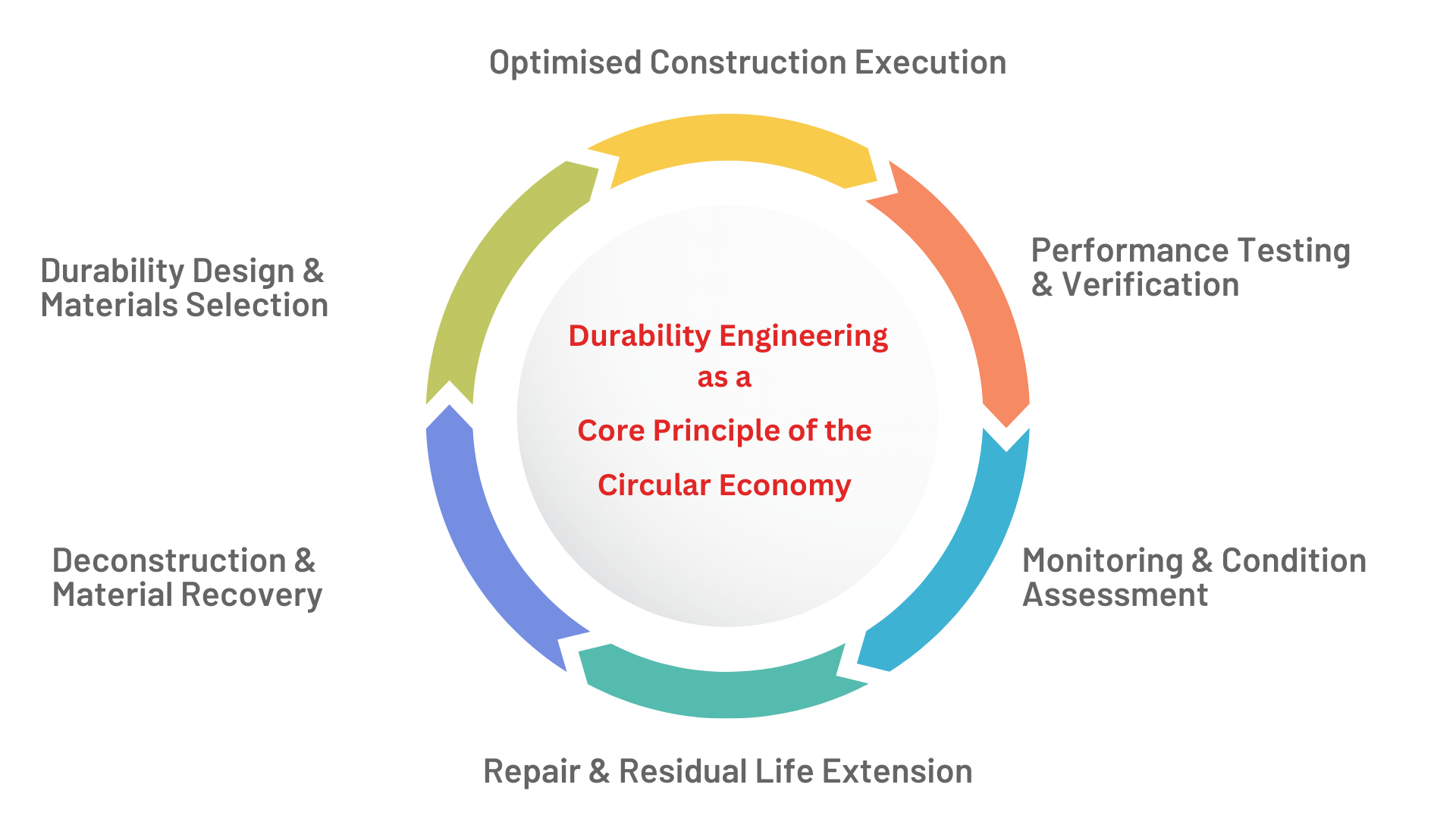
Ongoing Recommendations and Durability Strategy
To support continued structural integrity and long-term resilience, BCRC has developed a proactive remediation and maintenance strategy that includes:
· Prompt façade and masonry repairs to improve moisture resistance and visual integrity.
· Localised concrete remediation in the affected unit to eliminate contamination risks.
· Continued condition monitoring across all critical structural elements throughout the redevelopment phase, ensuring adaptive management of the asset’s condition.
Future Outlook
By proactively addressing these recommendations, the 372- 382A Pitt Street redevelopment will successfully integrate historical architecture with contemporary construction practices. Ensuring structural durability remains paramount for the success of this iconic project.
For expert advice on durability and structural assessment, contact BCRC Durability Consultants today.